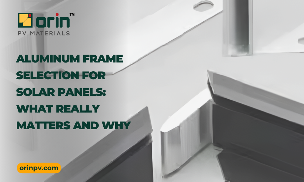
As solar modules become larger, thinner, and more powerful, the aluminum frame has evolved from a basic structural element into a key reliability driver. A well-designed frame directly influences mechanical strength, durability, safety, and long-term module performance.
With global solar manufacturing expanding rapidly, understanding why frames are designed the way they are has become essential — not only for frame manufacturers, but also for module producers, EPCs, and quality teams.
This article breaks down the critical engineering and design considerations behind modern aluminum solar frame selection.
1. Alloy Selection: Aluminum 6063 vs 6005A
Aluminum 6063 and Aluminum 6005A are the two most commonly used alloys for solar module frames. While 6005A is often considered the “stronger” alloy, real-world performance depends on more than alloy choice alone.
When properly processed and tempered (T5/T6), both 6063 and 6005A can achieve mechanical performance suitable for solar frame applications. Actual frame performance is governed by the combined effect of alloy chemistry, tempering practice, extrusion quality, profile geometry, and wall thickness.
Aluminum 6063:
• Excellent extrudability, enabling complex and thin-wall profiles
• Superior surface finish for high-quality anodizing
• Widely used and field-proven in solar applications
• Reliable strength when processed to T5/T6 temper
Aluminum 6005A:
• Slightly higher potential strength window
• More consistent mechanical properties in thicker sections
• Wider process tolerance during extrusion and heat treatment
• Often preferred for large-format modules or higher structural demand
Engineering Insight:
Frame performance is not determined by alloy alone. A well-designed and properly tempered 6063-T6 profile can outperform a poorly designed 6005A profile. Meanwhile, 6005A offers added manufacturing robustness and design margin for heavy-duty applications.
2. Flange Thickness
The flange is the section where mounting typically occurs.
On long frames:
• Clamps and mounting structures apply force here
• Insufficient thickness can lead to deformation or long-term fatigue
On short frames:
• Smaller flanges are acceptable
• Allows more rear-side light entry in bifacial modules
• Short sides are typically not used for mounting in standard industry practice
Design Consideration:
Flange thickness must balance mechanical strength and optical performance, especially for bifacial modules.
3. Wall Thickness
Wall thickness directly affects:
• Load-bearing capacity
• Resistance to bending under wind and snow loads
• Structural stability during transport and installation
Increasing wall thickness improves strength but also:
• Increases weight
• Raises material cost
This makes wall thickness optimization one of the most critical engineering decisions in frame design.
4. Glass Groove Design
The glass groove houses the glass laminate within the frame.
For a typical 2 mm glass-glass module:
• Industry-standard groove width: 6.1–6.2 mm
If the groove is too wide:
• Sealant may ooze out
• Poor bonding and cosmetic issues arise
If the groove is too narrow:
• Risk of glass breakage increases
• Especially critical with 2 mm semi-tempered glass
This becomes even more important when using edge clamps or UFO clamps. Insufficient sealant cushioning can cause stress concentration, leading to cracks or breakage.
5. Top Lip Width
The top lip covers the glass edge and contributes to strength and aesthetics.
• If too wide: causes cell shading and power loss
• If too narrow: reduces mechanical strength
Industry standard: 9–11 mm
This range balances mechanical integrity, optical performance, and visual appearance.
6. Sealant Reservoir
A sealant reservoir ensures:
• Adequate sealant remains on top of the glass
• Long-term protection against moisture ingress
Geometry is critical:
• Recess should avoid sharp curves or corners
• Sharp features cause stress concentration
When used with end clamps or UFO clamps, poor geometry increases glass breakage risk. Smooth, rounded profiles are always preferred.
7. Corner Key Design
Corner keys connect frame sections and significantly influence frame strength.
• Hollow corner keys provide better strength-to-weight ratio
• Deliver strong mechanical performance with reduced material usage
• More efficient and cost-effective than solid keys without compromising performance
8. Mounting, Drainage, and Earthing Holes
Mounting Holes:
• Standard diameters: 9–14 mm
• Tracker holes: 7–10 mm
• Typically two sets of mounting holes and one set of tracker holes
• Provided on long frames only
• Short frames are not conventionally mounted, though technically possible
Drainage Holes:
• Allow water to escape from frame cavities
• Minimum recommendation: 2 per frame
• Some designs use 4 per frame for improved water management
Preferred hole shapes:
• Rounded or curved cuts
• Avoid long rectangular cuts, which reduce frame strength
• Curved designs maintain mechanical integrity
Earthing Holes:
• Ensure proper electrical grounding
• Essential for system safety and compliance
9. X-Pitch (Distance Between Mounting Holes)
X-pitch selection depends on mounting structure design.
• If too small: frame strength reduces significantly
• Proper spacing ensures optimal load distribution
• Improves mechanical performance during load testing
10. Load Testing (IEC Standards)
Frames must be validated through mechanical load testing per IEC standards.
Typical test loads:
• Front-side (snow load): up to 5400 Pa
• Back-side (wind load): up to 2400 Pa
Some projects require higher loads based on geographic conditions.
Load-bearing capacity depends on:
• Mounting hole design
• X-pitch
• Wall thickness
• Alloy type
• Material hardness
• Overall frame geometry
Load testing ultimately validates the entire frame design as a system.
11. Ground Continuity
Ground continuity testing is required under IEC and UL standards.
• Aluminum frames generally pass naturally
• Failures occur only if:
– Improper anodizing in earthing zones
– Poor electrical continuity due to design or assembly issues
Good frame design ensures consistent grounding performance.
12. Anodizing Thickness and Performance
Anodizing protects frames from corrosion and environmental degradation.
Industry standard anodizing thickness: >15 microns
Benefits:
• Excellent corrosion resistance
• Weather protection for outdoor exposure
• Improved surface hardness
• Enhanced electrical insulation
Salt Mist Testing:
Validates corrosion resistance under coastal environments, high humidity, and corrosive atmospheric conditions. Proper anodizing shows minimal corrosion after extended exposure.
Dielectric Properties:
Anodized aluminum provides electrical insulation, prevents leakage currents, and enhances module safety compliance.
CONCLUSION
Solar frame design is far more than aluminum extrusion. It is a carefully engineered balance of mechanical strength, optical performance, durability, manufacturability, and compliance with international standards.
From alloy selection and wall thickness to groove dimensions and anodizing quality, every detail directly influences module performance and lifetime.
As solar modules continue evolving, larger, thinner, and more powerful, intelligent frame design remains a critical enabler of long-term reliability and bankability in the solar industry. At Orin PV Materials, we believe precision-engineered frame solutions play a vital role in supporting this next generation of high-performance modules.
Looking to optimize aluminum frame design for your next module program? Connect with our engineering team to explore precision-designed framing solutions for long term performance.